Introduction: Why Heat Dissipation Structure Is Critical for LED Floodlights
LED floodlights (especially high-power models 50W-500W) generate significant heat during operation—LED chips convert only 10-20% of energy into light, with the remaining 80-90% released as heat. For these fixtures, heat dissipation isn’t just a "support function"—it’s a core structural design that directly impacts performance, lifespan, and safety. A poor heat dissipation structure leads to chip junction temperature (Tj) exceeding 120°C, causing: ① 0.3-0.5% lumen depreciation per °C (e.g., 30% flux loss in 2 years); ② color temperature drift (Δu’v’ >0.007); ③ driver failure due to overheating; ④ even fire hazards in extreme cases. In contrast, a well-designed heat dissipation structure keeps Tj ≤85°C, ensuring LED floodlights maintain 90%+ initial brightness for 50,000+ hours. This blog analyzes the heat dissipation structure of LED floodlights in depth, exploring its design logic, key components, structural types, and optimization techniques.
Core Design Principles of LED Floodlight Heat Dissipation Structures
The heat dissipation structure of LED floodlights follows three fundamental engineering principles to achieve efficient heat transfer and dissipation:
- Heat conduction priority: Maximize thermal conductivity between LED chips and heat sinks to transfer heat rapidly from the heat source (chips) to the heat dissipation medium (heat sink).
- Heat dissipation area expansion: Increase the surface area of heat-dissipating components to enhance heat exchange with the surrounding air (convection heat transfer).
- Thermal resistance minimization: Reduce thermal resistance at every interface (chip-substrate, substrate-heat sink, heat sink-air) to avoid heat trapping—thermal resistance ≤2°C/W is the benchmark for high-power LED floodlights.
These principles guide the design of all key components in the heat dissipation structure, ensuring heat flows smoothly from the chip to the external environment without accumulation.
Key Components of LED Floodlight Heat Dissipation Structures
A complete heat dissipation structure of LED floodlights consists of five core components, each playing a unique role in the heat transfer chain:
1. LED Substrate (Heat Conduction Layer)
- Function: Act as the first-level heat conductor, transferring heat from LED chips to the heat sink. It’s the bridge between the chip (microscopic heat source) and the heat sink (macroscopic heat dissipation structure).
-
Common materials:
- Aluminum-based PCB (MCPCB): The most widely used substrate for LED floodlights, with thermal conductivity 1-4 W/(m·K) (standard grade) to 8-12 W/(m·K) (high-grade). It balances cost and performance, suitable for 50W-200W floodlights.
- Copper-based PCB: Thermal conductivity 20-40 W/(m·K), ideal for high-power (200W+) floodlights, but higher cost and weight.
- Ceramic substrate (Al₂O₃, AlN): Thermal conductivity 20-200 W/(m·K) (AlN), excellent insulation and heat conduction, used in ultra-high-power (300W+) or high-temperature environment floodlights.
- Design requirement: Substrate thickness ≥1.5mm (aluminum-based) to ensure structural stability and heat conduction efficiency; the copper layer (circuit layer) thickness ≥35μm to reduce thermal resistance.
2. Thermal Interface Material (TIM): Eliminating Air Gaps
- Function: Fill the micro-air gaps between the LED substrate and heat sink (air has extremely low thermal conductivity, ~0.026 W/(m·K)), reducing interface thermal resistance by 50-80%.
-
Common types:
- Thermal grease: High thermal conductivity (1-5 W/(m·K)), low cost, suitable for most floodlights. Requires uniform application (thickness 0.1-0.3mm) to avoid air bubbles.
- Phase-change material (PCM): Solid at room temperature, melts at 45-60°C (absorbing heat), thermal conductivity 2-8 W/(m·K). Automatically fills gaps, ideal for high-power floodlights with strict thermal requirements.
- Thermal pad: Flexible, easy to install, thermal conductivity 1-3 W/(m·K). Suitable for mass-produced floodlights, but slightly higher thermal resistance than grease/PCM.
- Critical index: Thermal conductivity ≥2 W/(m·K) for high-power floodlights; no volatilization or aging at 100°C+ (long-term operation temperature).
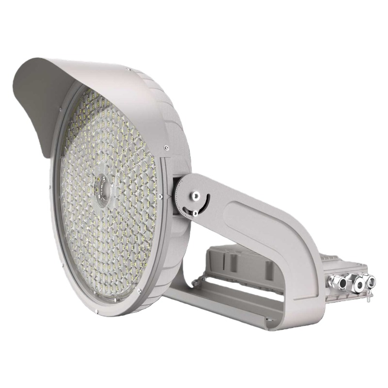
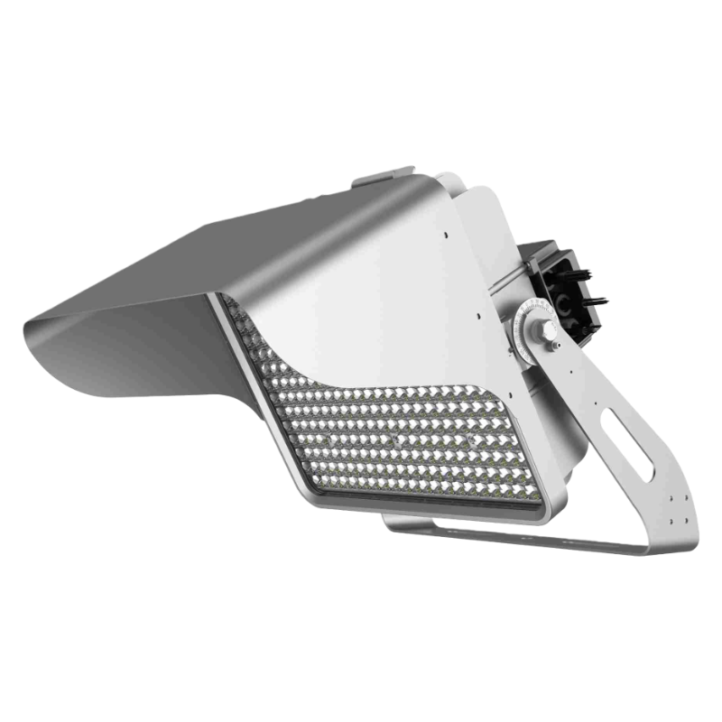
3. Heat Sink: Core Heat Dissipation Component
- Function: The "heat radiator" of LED floodlights, absorbing heat from the substrate and dissipating it to the air via convection (and radiation). It determines 70% of the overall heat dissipation efficiency.
-
Key design elements:
- Material: Die-cast aluminum (ADC12, A380) is the standard choice—thermal conductivity 96-110 W/(m·K), lightweight, and easy to form complex structures. For ultra-high-power models, 6063 aluminum alloy (thermal conductivity 201 W/(m·K)) is used for better heat conduction.
-
Structure type: Finned heat sinks are the most common (see "Structural Types" below), with fin height, spacing, and thickness directly affecting heat dissipation:
- Fin height: 20-60mm (higher = larger surface area, but excessive height reduces air flow).
- Fin spacing: 8-15mm (too narrow blocks air convection; too wide wastes space).
- Fin thickness: 1.5-3mm (balances structural strength and heat conduction).
- Surface treatment: Anodization (black or gray) increases emissivity (0.8-0.9 vs. 0.1-0.2 for bare aluminum), enhancing radiation heat transfer by 30-50%. Some high-end models use electrophoretic coating for better corrosion resistance (critical for coastal/industrial environments).
- Performance benchmark: Thermal resistance ≤1.5°C/W for 200W floodlights; surface area ≥0.5 m² (per 100W power).
4. Housing: Integrated Heat Dissipation & Protection
- Function: For most LED floodlights, the housing is integrated with the heat sink (one-piece die-casting) to avoid additional thermal resistance. It serves dual purposes: heat dissipation and environmental protection (dust, water).
-
Design requirements:
- Integration: No separate housing-heat sink connection (avoids interface thermal resistance). The housing’s inner surface is directly connected to the substrate via TIM.
- Airflow optimization: Open design (no closed cavities) to ensure air circulates around the fins. Some industrial floodlights add air guide grooves to enhance cross-ventilation.
- Material consistency: Same as heat sink (aluminum alloy) to maintain uniform thermal conductivity—avoid plastic housings for high-power floodlights (thermal conductivity ≤0.5 W/(m·K), trapping heat).
5. LED Driver Heat Dissipation
- Function: Drivers (especially high-power constant-current drivers) generate 5-10% of the total heat (e.g., a 200W driver with 95% efficiency produces 10W heat). Poor driver heat dissipation causes capacitor aging and circuit failure.
-
Integration methods:
- Integrated with main heat sink: The driver is mounted on the inner wall of the aluminum housing (heat sink), with TIM between the driver case and housing—heat is dissipated via the main heat sink.
- Independent heat sink: For 300W+ floodlights, the driver has a small dedicated finned heat sink, connected to the main heat sink via thermal straps.
- Key requirement: Driver operating temperature ≤70°C (capacitor lifespan doubles for every 10°C reduction).
Common Structural Types of LED Floodlight Heat Dissipation
Based on application scenarios and power levels, LED floodlights adopt three main heat dissipation structure types, each with unique advantages:
1. Passive Finned Heat Dissipation Structure (Most Widely Used)
- Design: One-piece die-cast aluminum housing with external fins (radial, linear, or honeycomb-shaped). Heat is dissipated via natural convection (air flows around fins) and radiation—no fans or moving parts.
- Advantages: Simple structure, low cost, high reliability (no fan failure), silent operation.
- Disadvantages: Lower heat dissipation efficiency than active structures, suitable for ≤300W floodlights.
- Typical application: Commercial parking lots, building facades, medium-power industrial yards.
- Optimization example: Radial fins (like a fan) enhance 360° air flow, improving convection efficiency by 20% compared to linear fins.
2. Active Heat Dissipation Structure (For Ultra-High Power)
- Design: Based on passive finned structure, adding a DC brushless fan (12V/24V) at the bottom or top of the heat sink. The fan forces air to flow through the fins, accelerating heat exchange.
- Advantages: Heat dissipation efficiency 2-3x higher than passive structures, suitable for 300W-500W floodlights (Tj can be reduced by 20-30°C).
- Disadvantages: Higher cost, fan lifespan (50,000-80,000 hours) limits overall fixture lifespan; requires waterproof design for outdoor use.
- Typical application: Large stadiums, high-power construction sites, ports (400W+ floodlights).
- Key design: Fan IP rating ≥IP65 (waterproof/dustproof); speed control (adjusts fan speed based on temperature) to reduce noise and energy consumption.
3. Heat Pipe-Assisted Heat Dissipation Structure (High-End & Special Environments)
- Design: Integrates heat pipes (copper tubes filled with working fluid, e.g., water, ethanol) into the finned heat sink. Heat pipes transfer heat from the substrate to the fins 10x faster than aluminum, reducing thermal resistance by 40-60%.
- Working principle: The evaporator section (connected to the substrate) absorbs heat, vaporizing the working fluid; the vapor flows to the condenser section (fins), releasing heat and condensing back to liquid; capillary force returns the liquid to the evaporator—cycle repeats.
- Advantages: Ultra-high heat dissipation efficiency, compact structure (fins can be smaller), suitable for high-power floodlights with space constraints.
- Disadvantages: High cost (heat pipes account for 30-40% of material cost), complex manufacturing.
- Typical application: Ultra-high-power stadium floodlights (500W+), enclosed industrial environments (poor air flow).
Key Optimization Strategies for Heat Dissipation Structures
To address the heat dissipation challenges of high-power LED floodlights (e.g., limited space, harsh environments), manufacturers adopt the following optimization strategies:
1. Thermal Simulation-Driven Design
Using finite element analysis (FEA) software (e.g., ANSYS Icepak, Fluent), simulate the heat flow of the entire structure before production. Optimize fin spacing, height, and heat pipe layout to minimize Tj—reducing prototype iteration time by 50% and improving heat dissipation efficiency by 15-20%.
2. Multi-Layer Heat Conduction Enhancement
For 300W+ floodlights, adopt a "chip-substrate-thermal pad-heat pipe-heat sink" multi-layer structure, with each layer’s thermal resistance strictly controlled:
- Chip-substrate: ≤0.2°C/W
- Substrate-thermal pad: ≤0.3°C/W
- Thermal pad-heat pipe: ≤0.1°C/W
- Heat pipe-heat sink: ≤0.5°C/W
Total thermal resistance ≤1.1°C/W, ensuring Tj ≤80°C for 300W operation.
3. Environmental Adaptation Optimization
- Coastal/industrial environments: Use 316L stainless steel screws and electrophoretic-coated heat sinks to prevent corrosion (corroded fins reduce surface area by 30%+).
- High-temperature areas (≥40°C): Increase fin height by 20% and add air guide grooves to enhance convection; use phase-change TIM to absorb sudden heat spikes.
- Dusty environments: Widen fin spacing to 12-15mm to avoid dust accumulation (dust layers reduce heat dissipation by 40% in 6 months).
4. Integration of Heat Dissipation & Optics
Avoid blocking fins with optical components (e.g., lenses, reflectors). Design the lens holder to be raised 10-15mm above the fins, ensuring air flow isn’t obstructed. Some models integrate the reflector into the heat sink (aluminum reflector with heat-conducting brackets), transferring reflector heat to the heat sink—preventing lens fogging from localized heat.
Real-World Case: Heat Dissipation Structure Optimization for 200W LED Floodlight
- Original structure problem: Linear fin heat sink (fin height 30mm, spacing 8mm), aluminum-based PCB (2 W/(m·K)), thermal grease (1.5 W/(m·K)). Tj reached 105°C during 24h operation—lumen depreciation of 15% in 1 year.
-
Optimization measures:
- Replace linear fins with radial fins (height 40mm, spacing 12mm)—surface area increased by 35%.
- Upgrade to high-grade aluminum-based PCB (6 W/(m·K)) and phase-change TIM (3 W/(m·K))—interface thermal resistance reduced by 40%.
- Anodize the heat sink (black) to enhance radiation heat transfer.
-
Optimization results:
- Tj dropped to 82°C (22% reduction).
- Lumen depreciation reduced to 5% in 1 year.
- Lifespan extended from 40,000 hours to 60,000 hours.
Conclusion: Heat Dissipation Structure Is the Foundation of LED Floodlight Reliability
The heat dissipation structure of LED floodlights is a systematic engineering design—integrating substrate, TIM, heat sink, housing, and driver heat dissipation into a cohesive heat transfer chain. For high-power floodlights, a well-designed structure isn’t just about "cooling down"—it’s about maintaining stable Tj, ensuring consistent brightness, extending lifespan, and avoiding safety hazards. By following the principles of heat conduction priority, area expansion, and thermal resistance minimization, and adopting passive/active/heat pipe structures based on power and environment, manufacturers can create LED floodlights that perform reliably in harsh conditions. For buyers and engineers, understanding the key components and optimization strategies of heat dissipation structures is essential for selecting and designing high-quality LED floodlights—proving that "good heat dissipation = long life + stable performance."